This page contains the schematics of the DIY waterdrop device. It is a collection of information I found on the internet and used to build my waterdrop device. Credits go to the original designers. Sometimes, it is hard to find specific component types, but usually, it is okay to use a similar type.
You can download the source code from the application page.
Table of Contents
- Arduino Uno
- Valve Control
- Flash and Shutter Control
- Voltage Regulator (5V and 9V)
- LCD Display
- Keypad Using One Analog Input Pin
- Sound Detection
Arduino Uno
You can find all necessary information on www.arduino.cc. I suggest buying a pre-built board from a local reseller. If you want to build it yourself, you can find the schematics on the Arduino website.
The Uno has just enough memory and ports. You need to program it efficiently, especially if you want to store settings in memory. If you need more memory and ports, consider buying the Mega. (I have connected a 20x4 LCD, a keypad, and the flash, shutter, sound, and valve triggers and still have ports available on the Uno.)
Valve Control
The Shako valve uses 24V DC. While I would prefer using 12V because it generates less heat in the voltage regulators, 24V still works. The Arduino cannot directly power the valve, so you need an electronic circuit.
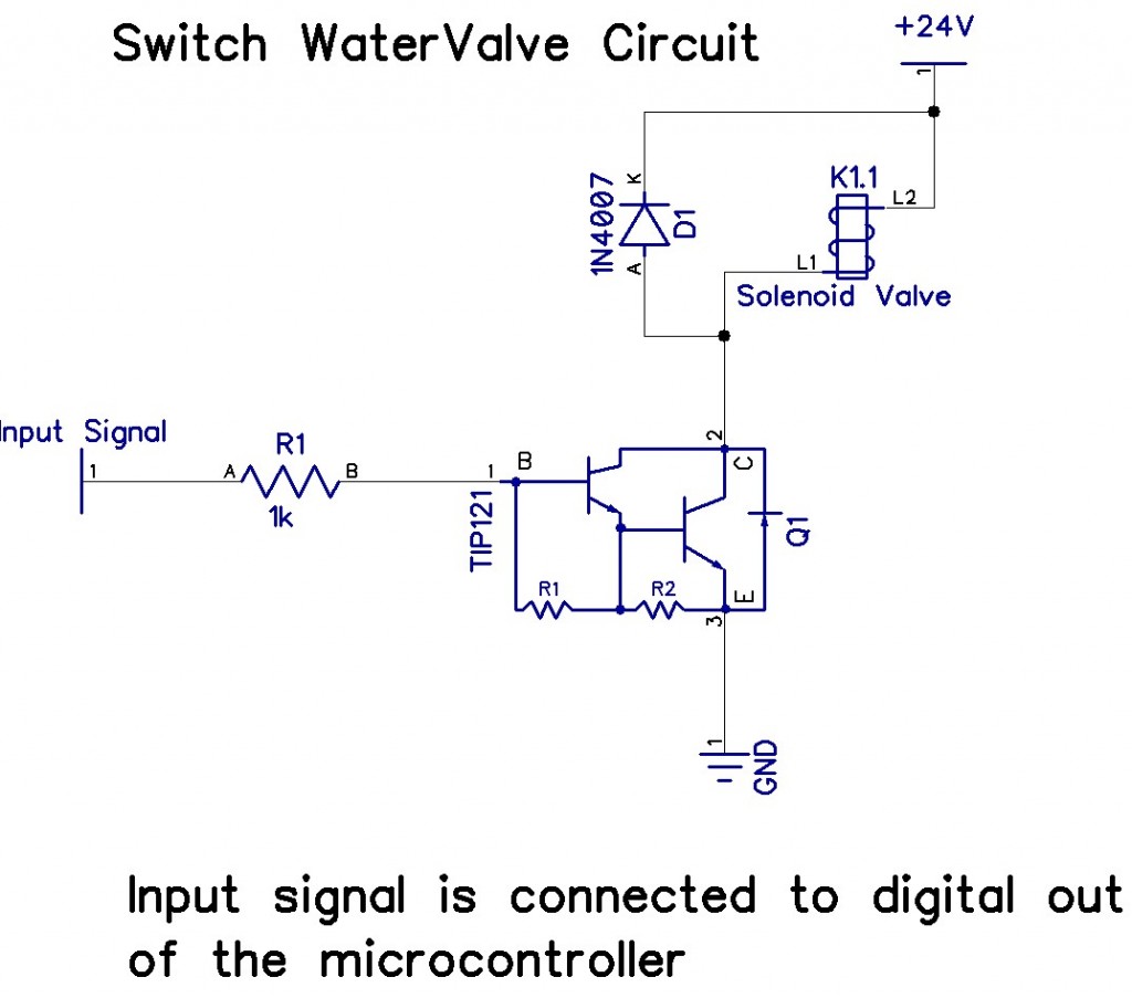
(Check the connection pins of the TIP121 or a compatible transistor carefully, as I am unsure if the pin numbers in the drawing are correct.)
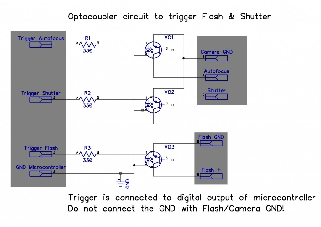
Flash and Shutter Control
Use three optocouplers of type 4N25 or an equivalent to trigger the flash and shutter. The main advantage of an optocoupler is the optical isolation between the flash and camera circuits and the microcontroller.
The schematic is designed for one flash and one camera. The shutter requires two optocouplers:
- One for autofocus
- One for the shutter
Even if you do not use autofocus, you must mimic the functionality of your camera’s shutter button:
- Half-press = autofocus
- Full-press = shutter
The third optocoupler triggers the external flash. If you need more flashes, extend the schematic accordingly. Keep the electronic circuits of the microcontroller, camera, and flash separate—do not connect the ground (GND) between the microcontroller, camera, and flash.
Each optocoupler is connected to a digital pin on the Arduino. Setting the pin high will turn on an LED inside the optocoupler, which activates the optical transistor. No external power is needed for the optocoupler to function.
⚠️ Important: An optocoupler can only handle a limited current. Do not use it to switch high currents. Modern flashes use about 6V to trigger, while older flashes may require up to 300V, which can damage the optocoupler. If you need to handle high voltages, search for specialized optocouplers designed for this purpose.
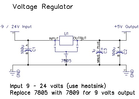
Voltage Regulator (5V and 9V)
 The Arduino can handle input voltages between 5V and 12V but operates most stably between 7V and 12V. Above 12V, the onboard voltage regulator may overheat.
My system operates at 24V DC because the valve requires 24V. To step down the voltage, I use three voltage levels:
- 24V DC (for the valve)
- 9V DC (for powering the Arduino Uno)
- 5V DC (for external circuits like the sound trigger)
I chose 9V for the Arduino because it is within its specifications and reduces the heat generated compared to using 12V. The Arduino has its own voltage regulator and outputs 5V on its digital pins, which is perfect for controlling components like optocouplers.
To power external devices, I use:
- 7805 voltage regulator for 5V
- 7809 voltage regulator for 9V
Ensure you use the 1A or 2A version of these regulators and attach a heatsink to prevent overheating.
- Capacitor C3 is an electrolytic capacitor (ELCO).
- The other capacitors are standard types—ask your supplier for recommendations.
LCD Display
Purchase an LCD display from eBay based on the HD44780 driver IC. Popular sizes include 16x2 and 20x4.
Connection:
- Connect RS, Enable, D4, D5, D6, and D7 to the Arduino.
- Connect R/W to ground (this allows writing to the display).
There are many online guides on how to connect an LCD display to the Arduino—Google for instructions.
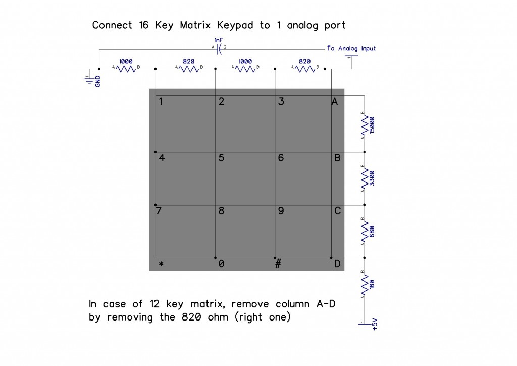
Keypad Using One Analog Input Pin
A matrix keypad is available on eBay for a few dollars. Normally, it requires multiple digital input pins, but using a voltage divider, you can read it using just one analog input pin.
How It Works:
- In software, read the analog pin value while pressing a key.
- Each key press corresponds to a specific voltage, which you can map in your code.
Most keypads have:
- 4 row pins
- 4 column pins
Use a multimeter to determine which pins are connected when pressing a button. I powered my keypad with 5V from the Arduino.
More details can be found on the Arduino Forum and similar websites.
Sound Detection
I built a sound detection circuit to trigger the flash upon detecting a noise.
In the end I never used it because it was not good enough. The schematics got lost so if you need this, use google.